For the complete documentation index, see llms.txt. This page is also available as Markdown.

Object Frames

The Object Frame layout element - connecting layouts to database objects and grouping graphic elements by borehole.

The Object Frame is the first required element on any layout. It connects the layout to actual database objects via drag-and-drop from the GeoDin Object Manager tree, and it groups the graphic elements that belong to one borehole (or a set of boreholes). All complex graphic elements - borehole log, depth scale, samples, groundwater, data sequence, well design - must be placed inside an object frame. See Creating Custom Layouts for the step-by-step walkthrough.

Working with object frames

Visual indicators

The object frame uses sphere icons to show its connection state:

  • White sphere - no database object connected; layout is in template mode.

  • Red sphere - a single database object is connected (single object frame).

  • Multiple spheres - multiple objects connected (multi-object frame).

Selected frames show 4 grey squares and 4 grey side lines. An unselected frame is represented by 4 grey angles at the corners.

Selecting a frame

The object frame is a special type - a further development - of the group frame. To select it, click in the boundary area of the frame, or hold the Ctrl key and click at any place inside the frame. The special features for the scaling of group frames are also available for object frames.

Data linking and drag-and-drop

Drag a database object from the GeoDin Object Manager onto the layout to link it to the object frame. Drag-and-dropping during layout editing is for editing-mode preview only - it does not permanently link objects to the template. The permanent data source for a layout run is set through the Data source branch in Object Properties.

For a Multi-Object Frame, hold the Command key while dragging to add multiple objects to the data source. The data source can be defined to specify exactly which boreholes to include in the output.

Graphic elements inside the frame

The geological graphic elements inside the object frame always refer to the borehole chosen by the frame. Individual graphic elements can be arranged in any way inside the frame - for example, a borehole log and a borehole table can be displayed side by side using the available labeling options.

The frame should be large enough to hold all the graphic elements it will contain. In most layouts it is recommended to draw the object frame to cover the entire page.

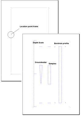
Object frame layout schematic
An object frame grouping the graphic elements of one borehole: one layout page highlights the location point frame; the second shows dashed placeholders for the depth scale, borehole profile, groundwater and samples elements.

Reference: Object Frame element

Frame types

Type
Description

Single Object Frame

Displays data from one database object (e.g., one borehole) at a time. A small red circle appears in the top-left corner when a database object is connected.

Multi-Object Frame

Displays data from multiple objects simultaneously (e.g., 5 borehole logs side by side). Hold Command while dragging to add objects to the data source.

An object frame therefore has to be drawn for each borehole if more than one borehole should be shown in one graph, unless a multi-object frame is used.

Position

Object frame position can be set exactly via Properties > Position > X, Y, Width, Height. For example, setting X=0, Y=0, Width=21 cm, Height=29.7 cm produces an A4 portrait frame covering the full page.

Converting between frame types

An object frame can be converted to or from a multi-object frame. Select the frame, right-click, and choose Convert Object Frame. After confirmation, the frame is converted.

Last updated

Was this helpful?